VT-AJV Probable Cause Analysis: When Weather Radar Fails in Convective Environments
The Accident
On 23 February 2026, a Beechcraft King Air C-90A (VT-AJV), operated by Redbird Airways as a non-scheduled air ambulance flight from Ranchi (VERC) to New Delhi (VIDP), crashed near Kasiyatu village in Chatra District, Jharkhand. All seven persons on board — two pilots, two medical personnel, one patient, and two attendants — were killed. The aircraft was destroyed.
The wreckage was scattered over approximately one kilometre of densely forested terrain in the Chota Nagpur Plateau, with both engines found separated from the wings hundreds of metres from the main crash site. The pattern told an unmistakable story: this aircraft broke apart in flight.

This map shows the full planned route from Ranchi (VERC) to New Delhi (VIDP) as a yellow dashed line passing through seven waypoints. The green solid line shows the aircraft’s actual track — departing northward on heading 329° rather than following the planned route westward. The red X marks the crash site at 23°57′N, 84°54′E, approximately 75 km north-northwest of Ranchi. The blue shaded areas represent the cumulonimbus (CB) cells that were active to the west and northwest of Ranchi, directly along the planned departure route on W109. The CB activity forced the crew into progressive rightward deviations that ultimately led them into the convective system from a different angle.
A Sequence of Weather Deviations
The flight timeline reveals a crew progressively retreating from convective weather they could not outmanoeuvre:
| UTC | IST | Event |
|---|---|---|
| 1337 | 1907 | Take-off from Ranchi Rwy 31 on track 313° (deviation from assigned W109/297° due to weather) |
| 1339 | 1909 | First contact ATC Kolkata; passing 5,000 ft, 7 NM out |
| 1345 | 1915 | Requested right heading 330° due to weather — approved |
| 1348 | 1918 | Requested level-off at FL140 |
| 1349 | 1919 | Last transmission; acknowledged instruction to contact Varanasi |
| ~1354 | ~1924 | Estimated time of crash. No further transmissions. |
The pattern is stark: three progressive rightward deviations — from the assigned 297° to runway heading 313° to 330° — all within 12 minutes of take-off. This is not the behaviour of a crew with a functioning weather radar showing them a clear path. This is a crew following the visible edge of cloud, reacting to what they can see out of the windshield, and being drawn inexorably into the convective system they were trying to avoid.
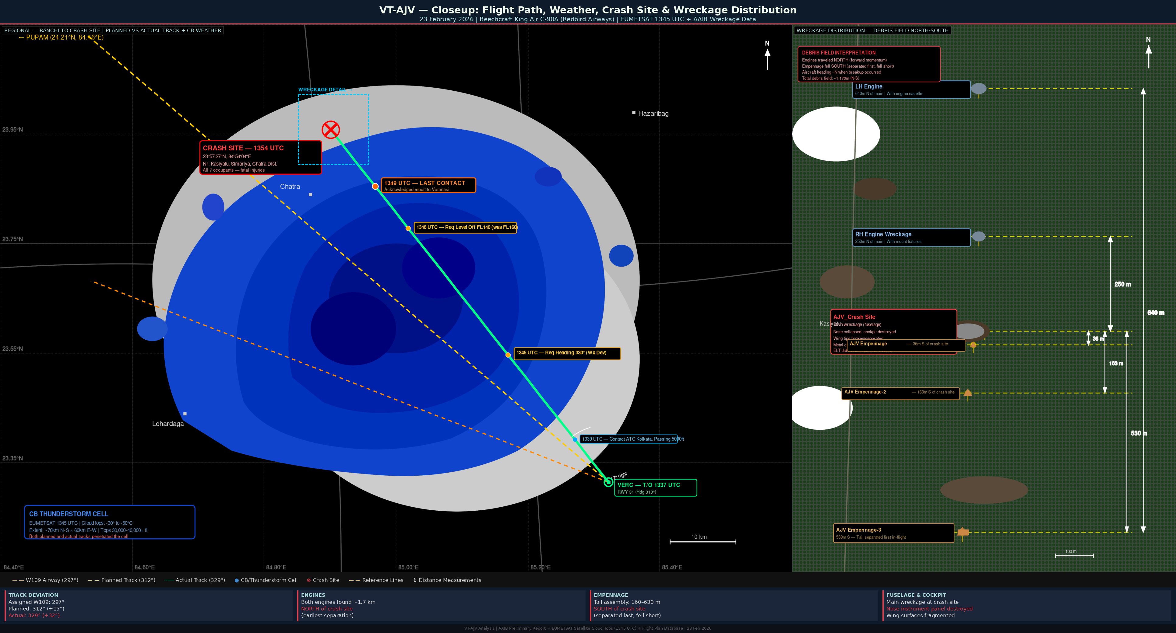
The left panel shows the three tracks from Ranchi: the assigned airway W109 at 297° (orange dashed), the planned route to waypoint PUPAM at 312° (yellow dashed), and the actual flown track at 329° (green solid). The CB cell matching EUMETSAT satellite data is shown in the area where the tracks converge. The right panel maps wreckage distribution across the forested terrain near Chatra, showing the breakup sequence from engines to fuselage.
The Weather: CB Activity Building to the West
The METAR sequence from Ranchi paints a picture of rapidly escalating convective activity:
| UTC | Wind | Vis | Wx | Cloud |
|---|---|---|---|---|
| 1300 | 070/03 | 5000m | HZ | BKN 10,000 ft |
| 1330 | 060/03 | 4500m | HZ | FEW CB 3000 ft (CB to W) |
| 1400 | 160/04 | 4000m | HZ | FEW CB 3000 ft (CB to W) |
| 1430 | 300/16 | 3500m | TS | FEW CB 3000 ft, TEMPO TSRA (CB to W, NW) |
Between 1400 and 1430 UTC, the surface wind at Ranchi shifted from 160°/04 kt to 300°/16 kt — a 140° directional shift with fourfold speed increase. This is a textbook thunderstorm gust front signature. The CB activity that had been to the west was now extending northwest, directly across the aircraft’s deviation route.
The freezing level was at FL130. The aircraft was climbing through FL140 — right at the interface of liquid and ice phases within the cumulonimbus, where turbulence intensity is at its maximum.
The Critical Question: Where Was the Weather Radar?
This 1987-vintage King Air C-90A would typically have been equipped with a Collins WXR-270 CLR or comparable magnetron-based weather radar. The central question of this analysis is why the crew flew into a severe CB cell. Five lines of reasoning point to the weather radar being non-functional, degraded, or misinterpreted:
1. Visual Avoidance, Not Radar-Guided Avoidance
A crew with an accurate radar picture showing the extent of the convective system would have requested a specific circumnavigation route or returned to Ranchi. Instead, the incremental, reactive heading changes (297° → 313° → 330°) are characteristic of pilots following the visible edge of cloud — the classic and often fatal technique of trying to “pick your way around” weather by eye.
2. 1987-Era Radar Limitations
The WXR-270 CLR is a magnetron-based system that requires manual tilt management and provides no vertical profiling. If the tilt angle was even slightly off during the climb, the radar beam could overshoot the weather entirely, painting a clear display while the aircraft was heading straight into a mature CB cell.
3. The Attenuation Trap
Older weather radars are susceptible to attenuation — where a near-field precipitation cell absorbs radar energy, making severe weather behind it appear weaker or invisible. A moderate rain area between the aircraft and a more intense CB core would create the appearance of a navigable gap on the radar display. This “false gap” phenomenon has been a contributing factor in numerous CB-penetration accidents worldwide.
4. Possible Equipment Degradation
With 6,613 airframe hours on a 1987 radar system, degraded magnetron output, faulty waveguide connections, or an intermittently functioning display are all realistic possibilities — conditions that might pass routine checks but fail when confronted with actual severe weather.
5. No Supplementary Lightning Detection
There is no indication the aircraft had a Stormscope or equivalent lightning detection system — equipment that would have provided an independent, radar-agnostic warning of electrical convective activity directly ahead.
The Wreckage Tells the Story
The wreckage distribution is the most compelling physical evidence of what happened in the aircraft’s final moments:
| Component | Location | Significance |
|---|---|---|
| LH Engine + Nacelle | 640 m North | Heaviest component; carried farthest by forward momentum |
| RH Engine + Fixtures | 250 m North | Second heaviest; separated with mounting hardware |
| Main Wreckage | Crash Site | Nose collapsed vertically; cockpit destroyed |
| Empennage (3 pieces) | 36–530 m South | Separated first, fell with less forward momentum |
Heavy components (engines) travelled north — in the direction of flight. Light components (tail fragments) fell short, south of the crash site. This distribution is physically impossible from a single ground-impact event and conclusively demonstrates in-flight structural breakup.
Annotated Wreckage Evidence
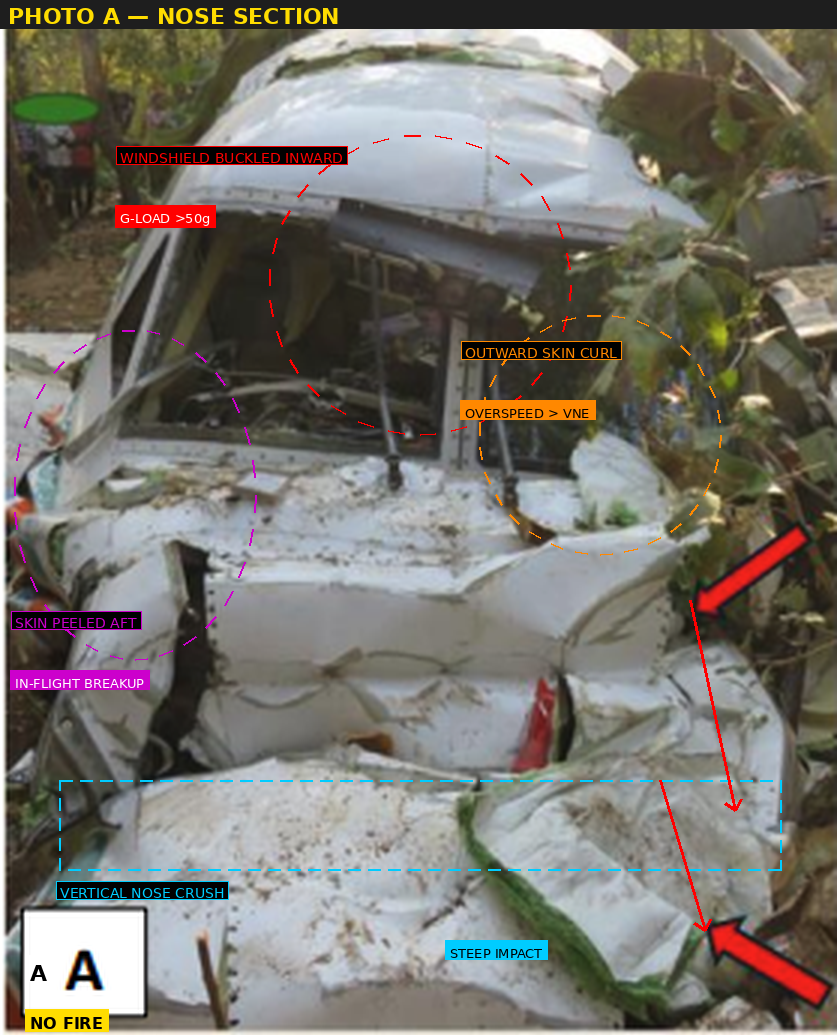
The nose section shows catastrophic vertical crush from a steep, high-speed ground impact. The red dashed circle highlights the windshield buckled inward — evidence of extreme deceleration exceeding 50g. The orange circle marks outward skin curling, a signature of aerodynamic loads exceeding the aircraft’s VNE (velocity never exceed). Magenta markers on the left indicate skin peeled aft, consistent with in-flight aerodynamic stripping. The cyan dashed line at the bottom indicates the vertical crush plane, confirming a near-vertical impact trajectory. The yellow NO FIRE tag confirms the complete absence of thermal damage.
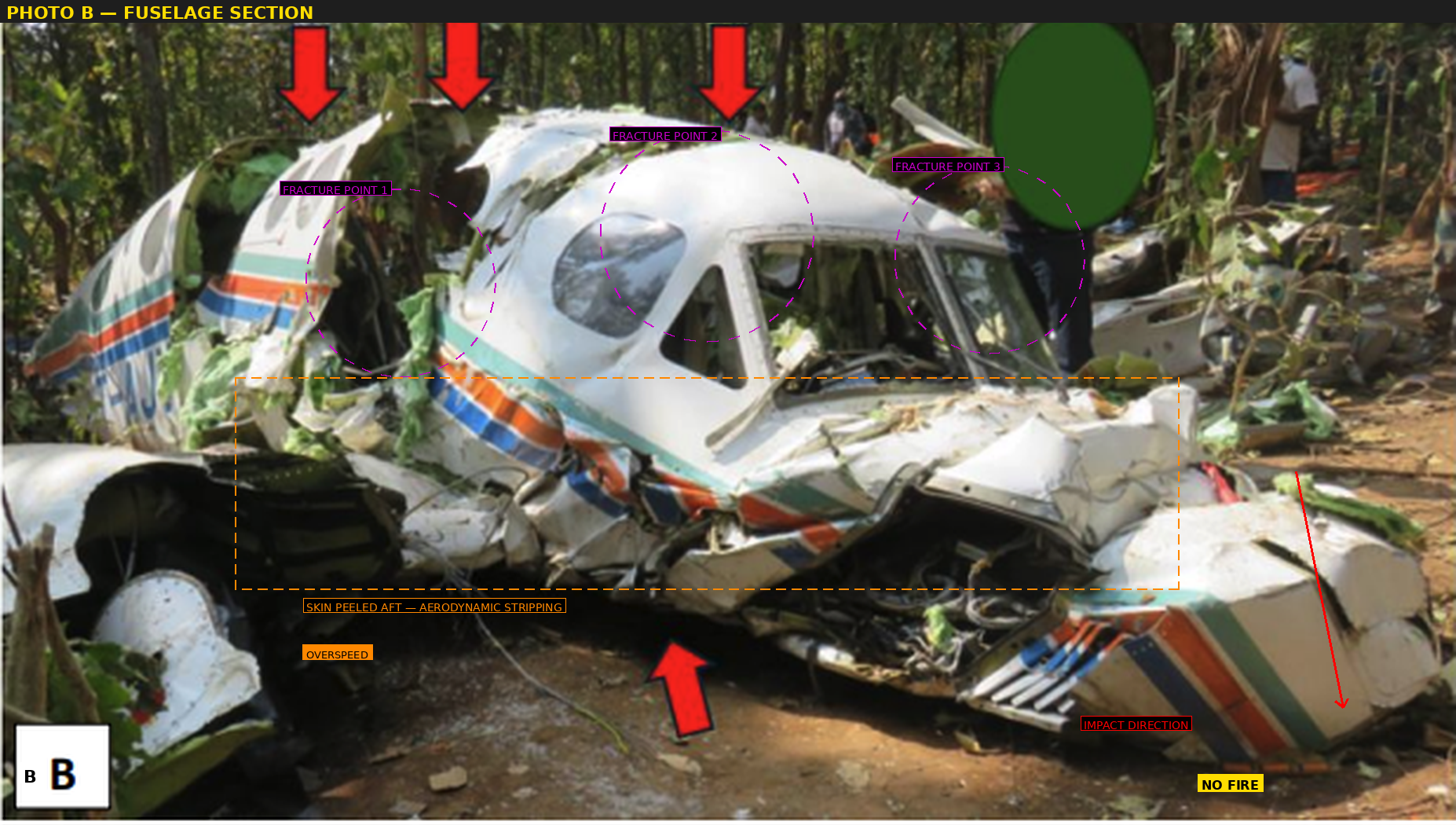
The fuselage exhibits multiple fracture points along its length, marked by magenta circles indicating in-flight structural failure at several stations. Orange markers highlight skin panels peeled aft by aerodynamic forces during the uncontrolled descent. Red arrows point to the fracture lines where the fuselage structure failed under loads exceeding design limits. The pattern of multiple distributed fractures — rather than a single impact break — is characteristic of progressive in-flight disintegration.
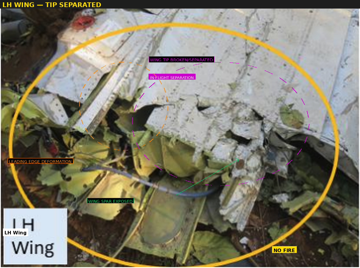
The left-hand wing shows the wing tip broken and separated from the main wing structure (magenta circle), evidence of aerodynamic overstress during the uncontrolled descent. Orange markers highlight leading edge deformation consistent with high-speed airflow impact. The structural deformation pattern indicates loads well beyond the wing’s design envelope.
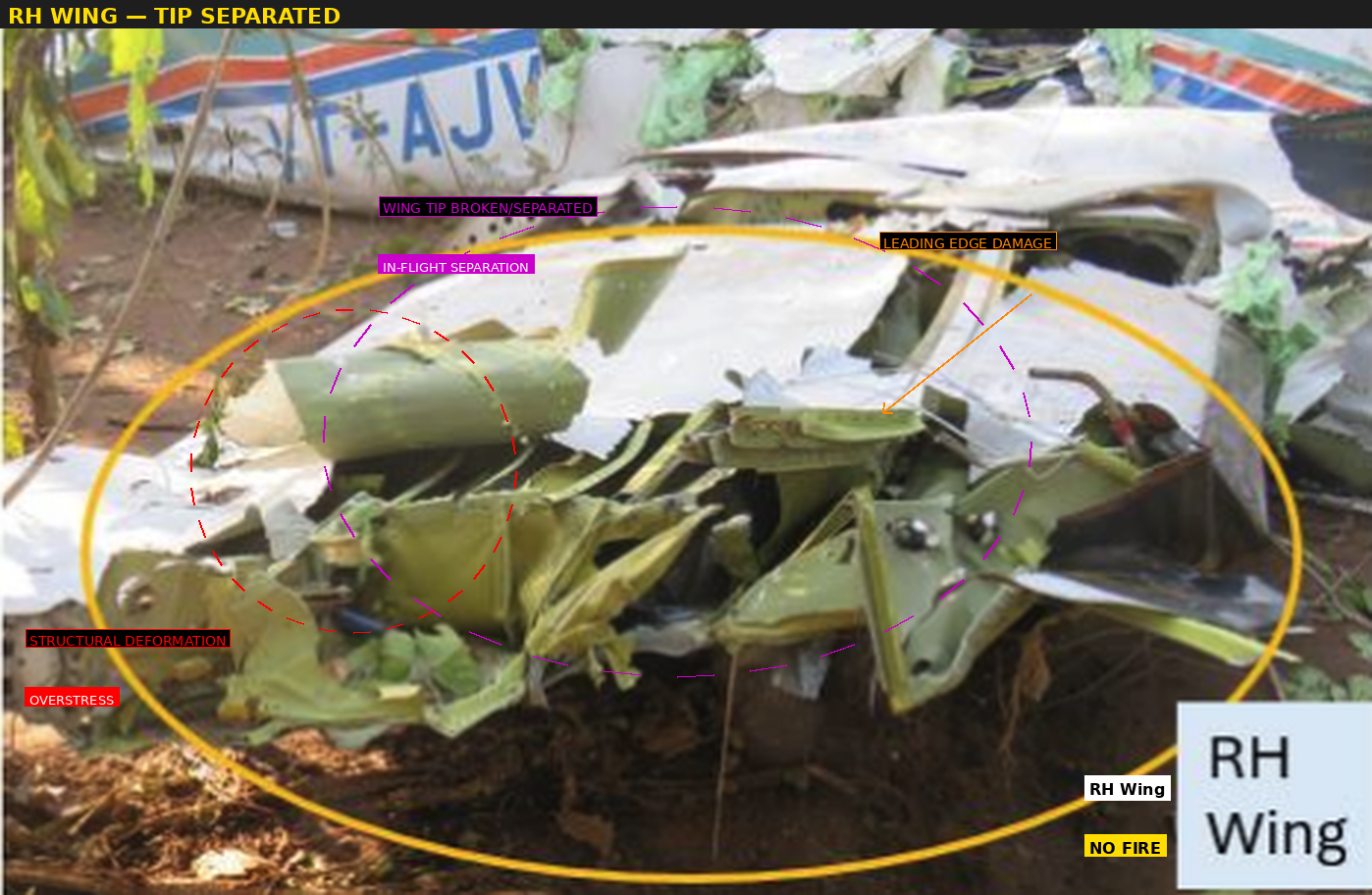
The right-hand wing displays similar damage to the LH wing — tip separated (magenta), structural deformation from overstress (red), and leading edge damage (orange). The symmetrical nature of wing tip failures on both sides is consistent with symmetric overload from vertical gust loads rather than asymmetric manoeuvre loads.

The cockpit reveals complete destruction of the instrument panel. The red dashed circle marks the area where instruments were ejected from their mounts by extreme deceleration forces. The cyan rectangle outlines the instrument panel area where all glass has shattered. The red dashed line at the bottom shows the control columns collapsed forward — physical evidence of a nose-down, high-speed impact. The yellow tag confirms no soot or thermal residue, definitively ruling out fire.
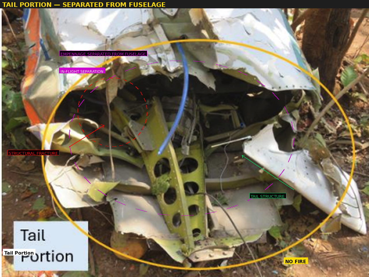
The tail section is shown separated from the main fuselage, with magenta markers indicating the fracture point where in-flight separation occurred. Red markers highlight the structural failure zone. The clean separation — without burn marks or melting — confirms mechanical failure from aerodynamic overload rather than any thermal event.
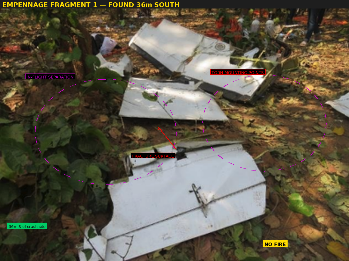
This empennage fragment, found 36 m south of the main wreckage, shows torn mounting points (red circles) where it separated from the fuselage in flight. The magenta markers indicate the in-flight separation surfaces. Green callouts identify the lightweight structural members. Found south of the crash site — opposite to the direction of flight — this fragment fell with minimal forward momentum after separating at altitude.
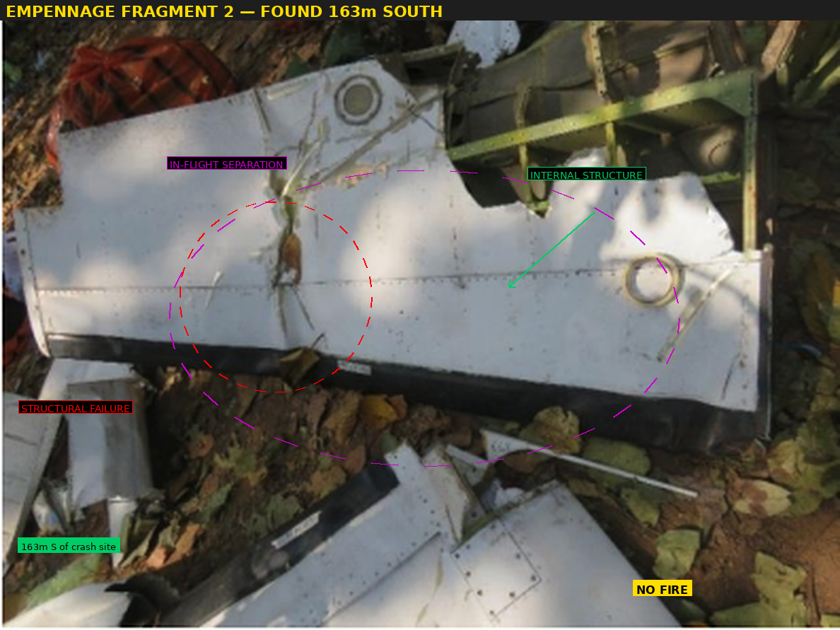
The second empennage fragment, recovered 163 m south of the crash site, shows similar in-flight separation characteristics. The structural failure patterns (red) and separation surfaces (magenta) are consistent with the tail section breaking apart progressively during the aircraft’s uncontrolled descent. The greater distance south compared to Fragment 1 suggests it may have separated at a slightly different altitude or was carried by upper-level winds.
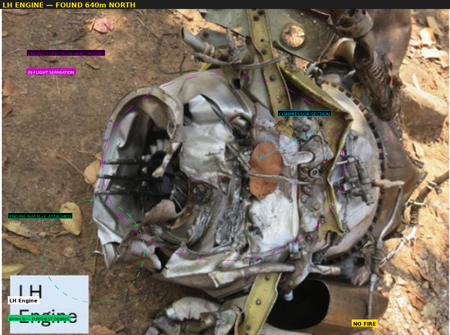
The left-hand engine was found 640 metres north of the crash site — the furthest piece of debris from the main wreckage. The magenta dashed circle highlights where the engine was torn from its wing mount during in-flight separation. Green markers identify the engine nacelle, which remained attached to the engine after separation. As the heaviest single component, the engine’s forward momentum carried it the greatest distance in the direction of flight. The 640 m separation distance is compelling evidence of high-altitude, high-speed breakup.
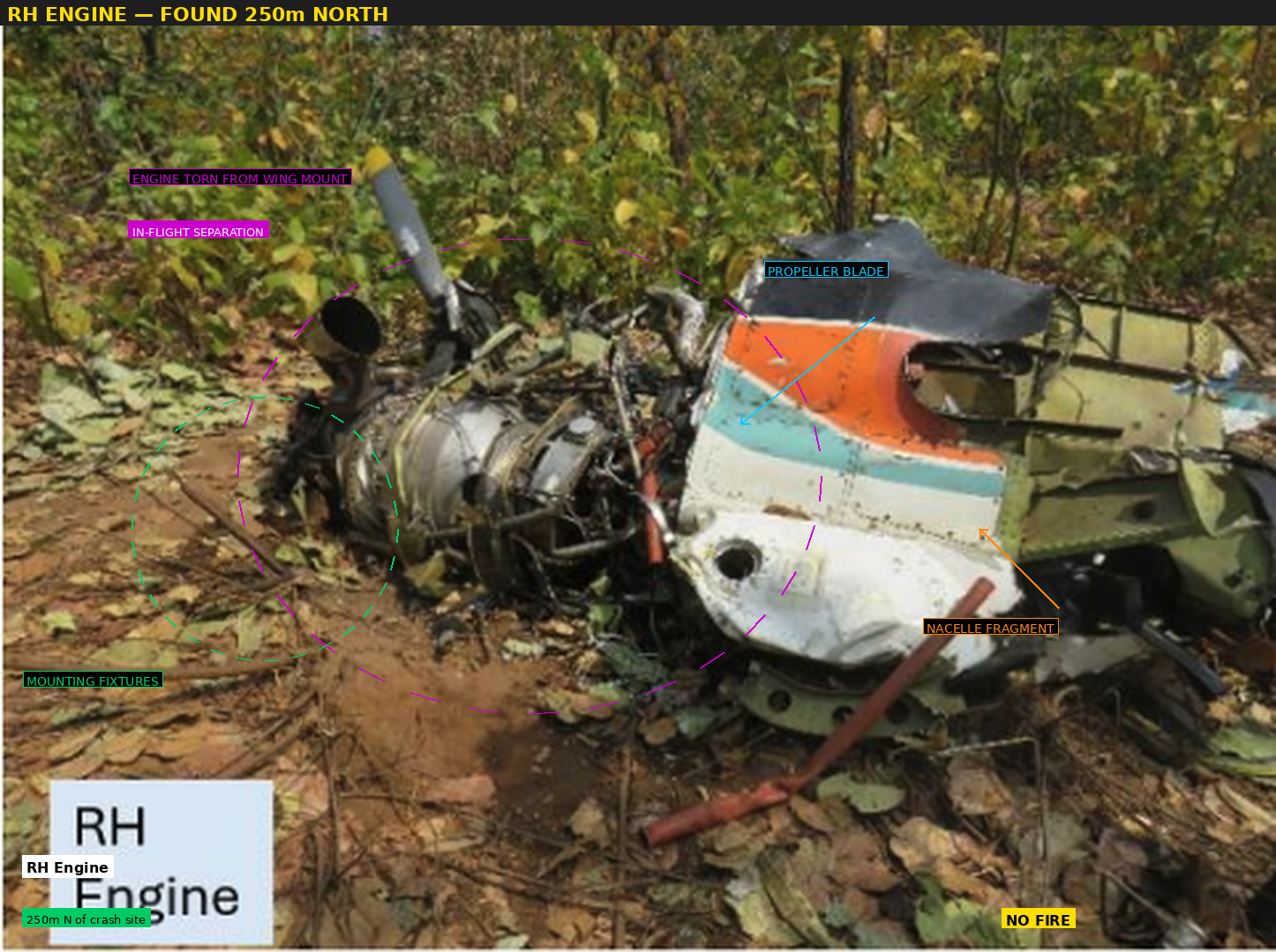
The right-hand engine, found 250 metres north, shows similar separation characteristics to the LH engine. Magenta markers indicate the torn wing mount attachment points. Green callouts identify the mounting fixtures that were found with the engine. The shorter travel distance compared to the LH engine (250 m vs 640 m) suggests it may have separated at a lower altitude or speed, or at a different point in the breakup sequence.
Critically, no soot, thermal discolouration, or burn marks were found on any component. In-flight fire and post-impact fire are definitively ruled out.
The Breakup Sequence
Reconstructing from the wreckage pattern:
Phase 1 — Turbulence Encounter: Aircraft enters extreme turbulence within a CB cell near FL140. Vertical gust loads exceed structural limits (+3.8g / −1.52g for Normal category).
Phase 2 — Empennage Separation: Tail section fails first under extreme flutter and bending loads. Aircraft becomes uncontrollable.
Phase 3 — Engine Separation: In the uncontrolled dive, overspeed develops. Aerodynamic forces tear both engines from their wing mounts.
Phase 4 — Ground Impact: The remaining structure impacts terrain at steep angle and very high speed. Near-vertical impact, no fire.
The Human Factors Dimension
The PIC was 25 years old with 306 hours PIC on type. The First Officer had zero PIC time on type and only 300 total hours. While both held valid licenses, this experience profile raises concerns about crew resource management in rapidly deteriorating weather.
This was an air ambulance flight with a patient on board — a context well-documented for introducing mission-completion bias, where the perceived urgency of the mission causes crews to accept risk they would otherwise reject. The decision to depart into known CB activity rather than hold on the ground or return to Ranchi may reflect this pressure.
The Absence of Data
VT-AJV was not equipped with a CVR or FDR. The ELT did not activate. This means investigators have no cockpit audio to determine what the crew discussed about the weather, no flight data to reconstruct the exact trajectory and structural failure sequence, and no confirmation of whether the weather radar was operating or what it showed. For accident investigation, this is a crippling data void.
PROBABLE CAUSE
The accident was caused by the in-flight structural breakup of the aircraft due to encounter with severe convective weather (cumulonimbus activity) during the climb phase of flight, resulting in aerodynamic loads that exceeded the aircraft’s structural design limits.
There is reasonable probability that the aircraft’s weather radar was either non-functional, providing an inaccurate depiction of the convective threat (due to equipment age, magnetron degradation, attenuation effects, or incorrect tilt management), or was not being utilised effectively. The crew’s progressive, reactive heading deviations — rather than planned circumnavigation — resulted in the aircraft penetrating a severe CB cell.
Safety Recommendations
This accident highlights five areas requiring urgent attention:
1. Weather Radar Serviceability: Periodic performance verification of weather radar systems, with mandatory minimum detectable reflectivity standards. Systems older than 15 years should demonstrate equivalence to modern solid-state radar or be upgraded.
2. Supplementary Weather Detection: Lightning detection systems (Stormscope or equivalent) should be required for air ambulance and non-scheduled IFR operations in convective weather regions.
3. CVR/FDR for Air Ambulance Flights: The CVR/FDR mandate should be expanded to include all air ambulance operations regardless of aircraft weight.
4. Convective Weather Training: Specific training on radar interpretation and limitations, CB recognition from METAR/TAF data, and mission-completion bias recognition.
5. Minimum Crew Experience: Review of minimum PIC experience thresholds for air ambulance captains, recognising the elevated operational demands.
This analysis is based on the AAIB Preliminary Report for VT-AJV. The official investigation is ongoing.
Published by SafetyMatters.co.in — April 2026
For safety education and awareness. Not for apportionment of blame or liability.
Discover more from Safety Matters Foundation
Subscribe to get the latest posts sent to your email.

