


Flight AI171 : Analysing Electrical System Anomalies
Table of Contents
Executive Summary
On June 12, 2025, Air India Flight AI171, a Boeing 787-8 (VT-ANB), experienced a catastrophic accident shortly after takeoff from Ahmedabad, resulting in the aircraft’s destruction and multiple fatalities.1 The wreckage, including significant structural and fire damage to buildings, was spread across a wide area, as depicted in post-impact imagery. The preliminary investigation points to an uncommanded dual-engine shutdown as the initiating event.
A primary theory under examination attributes this shutdown to an electrical disturbance that caused the Full Authority Digital Engine Control (FADEC) systems to interpret a loss of the “RUN” signal, thereby commanding fuel cutoff. This interpretation is supported by pre-existing Bus Power Control Unit (BPCU) gateway faults and the engines’ subsequent automatic relight attempts. The Flight Data Recorder (FDR) captured these transitions of the fuel cutoff switches, reflecting the commanded state as interpreted by the aircraft’s digital systems, rather than direct physical manipulation by the crew.

Further, the investigation encountered challenges in data retrieval from the aft Enhanced Airborne Flight Recorder (EAFR) due to extensive thermal and impact damage. While a theory suggested internal lithium-ion battery fire as the cause of this damage, a detailed review of the aircraft’s architecture indicates that the lithium-ion Recorder Independent Power Supply (RIPS) battery is located in the forward EAFR, not the aft unit.
Analysis of the aft EAFR revealed a critical soot discrepancy: while surrounding surfaces were soot covered from a carbon-rich combustion environment, the burnt EAFR casing itself appeared clean of soot, lacking carbonaceous deposits. This disparity suggests a Jet-A fuel pool fire or a localised structural/wood fire did not damage the EAFR. Instead, it points to a clean-burning thermal exposure, likely from a metal-fed fire (e.g., magnesium, aluminium alloy) or an electrical arc flash, consistent with high-temperature but short-duration or contained heat.4
This reinforces the suspicion of an electrical thermal origin or localised metallic combustion in the tail section, rather than full-scale external flame impingement from Jet-A pool fires. This report provides a detailed technical examination of these theories, integrating available flight data, system context, and preliminary findings, while emphasizing the ongoing nature of the investigation.
1. Introduction
Incident Overview
Air India Flight AI171, operated by a Boeing 787-8 Dreamliner with registration VT-ANB, suffered a catastrophic accident on June 12, 2025. The aircraft crashed shortly after its takeoff from Sardar Vallabhbhai Patel International Airport in Ahmedabad, India.1 The impact led to the complete destruction of the aircraft and resulted in multiple fatalities, including passengers, crew, and individuals on the ground.2
Post-impact imagery shows the extensive damage to the buildings and the surrounding area, with emergency services engaged in firefighting efforts. The wreckage was widely distributed, with significant parts of the aircraft, including the tail section and engines, found embedded in or near buildings . This incident occurred during the critical initial climb phase of flight, a period demanding maximum engine performance and posing heightened vulnerability to any system anomaly.1
Purpose of Report
The objective of this report is to provide a comprehensive and in-depth technical examination of the AI171 accident. It integrates all available data, previous discussions, and prevailing theories to present a detailed analysis. The primary focus areas include the uncommanded dual engine shutdown, which is strongly linked to an electrical disturbance within the aircraft’s sophisticated systems, and the severe thermal damage observed on the aft Enhanced Airborne Flight Recorder (EAFR), which complicated data recovery efforts. This analysis aims to clarify the technical nuances of the event sequence and highlight areas requiring further investigation.
2. Aircraft and System Context
Boeing 787-8 and GEnx-1B Engines
The accident aircraft, a Boeing 787-8 Dreamliner, is a modern wide-body jet renowned for its “more-electric” system architecture, which significantly reduces reliance on pneumatic systems for various aircraft functions.8 This design choice enhances fuel efficiency and reduces maintenance requirements. The aircraft was powered by two General Electric (GE) GEnx-1B turbofan engines.10 These engines are part of the GEnx family, designed for medium-capacity wide-body aircraft like the 787, and operate within a thrust category ranging from 69,800 to 76,100 lbf.11
Key Systems Involved
The Boeing 787’s advanced design incorporates several highly integrated systems critical to its operation, particularly its electrical and engine control functions.
- Full Authority Digital Engine Control (FADEC) / Electronic Engine Controller (EEC): The FADEC, often referred to as the “brain” of the engine, is a sophisticated, computer-based system that autonomously manages all aspects of engine performance, from thrust to fuel flow and ignition. 13 This includes precise control over fuel flow, ignition, and thrust settings.14 A key characteristic of a true FADEC system is the absence of manual override, placing full authority over the operating parameters of the engine in the hands of the computer.14 The FADEC receives and analyzes numerous input variables, such as air density, throttle lever position, engine temperatures, and pressures, up to 70 times per second.14 Its programming ensures optimal engine efficiency and provides automatic protection against out-of-tolerance operations.14 Critically, the FADEC also controls engine starting and restarting.14 In the context of this incident, the FADEC’s design means that it will interpret the absence or invalidity of the “RUN” signal as a command to shut down the engine, even if the physical fuel control switch is not manually moved.15
- Bus Power Control Units (BPCUs): BPCUs are fundamental to the 787’s electrical power distribution system.9 They act as central interfaces, managing the flow of power and control signals throughout the aircraft. Their functions include commanding relays, breakers, and contactors, and executing load shed management.9 BPCUs communicate with Generator Control Units (GCUs) and other systems primarily via the Common Data Network (CDN) and an isolated data bus.9 Given their role in routing critical data and power, BPCUs are vital for the integrity of the aircraft’s electrical and control systems, making any faults within them a significant concern for overall system stability.25
- Ram Air Turbine (RAT): The RAT is an emergency power source designed to deploy automatically under specific, critical conditions.2 These triggers include the loss of all engines, critically low RPM, or a total loss of all hydraulic or electrical power.6 Once deployed, the RAT utilizes the airstream to generate power, supplying hydraulic power to critical flight controls within a maximum of 6 seconds and electrical power within a maximum of 10 seconds.8 The BPCU or the Hydraulic Interface Function (HYDIF) can initiate RAT deployment.33
- Electrical System Architecture: The 787’s “more-electric” design means it generates and distributes a substantial amount of electrical power. This is achieved through six generators: two on each engine and two on the Auxiliary Power Unit (APU) located in the tail.8 Power is distributed across 235V AC and 28V DC buses 8, managed by various power conversion panels (P100-P800) and units like Autotransformer Rectifier Units (ATRU) and Transformer Rectifier Units (TRU).9 The Common Data Network (CDN), an ARINC 664 / AFDX fiber optic backbone, serves as the primary communication network, connecting various avionics units, including the flight data recorders, and significantly reducing wiring complexity.9 This network is crucial for transmitting flight-critical data, including airspeed, altitude, attitude, and engine operation.26
Sample Rates of FDR Parameters
Flight Data Recorders (FDRs) on the Boeing 787 typically sample digital parameters, such as the status of fuel valves, at a rate of 1 Hz, meaning one sample per second.35 This sampling rate implies that recorded timestamps for state changes are provided in whole seconds.37 While this provides a general sequence, it can introduce ambiguity regarding the precise sub-second timing of events. For instance, a recorded transition at 08:08:42 UTC means the actual event occurred anywhere between 08:08:42.00 and 08:08:42.99 UTC, potentially obscuring very rapid, near-simultaneous occurrences.37
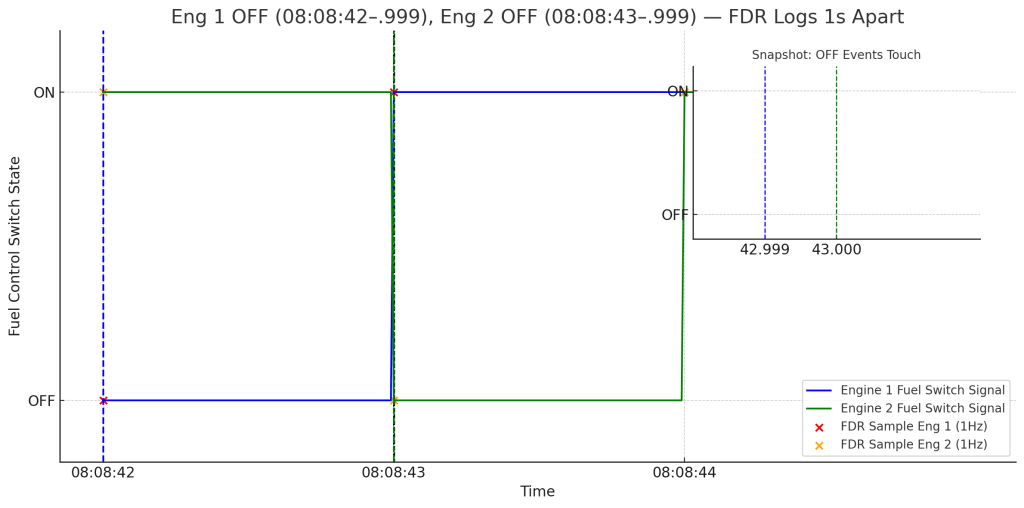
Table 1: Boeing 787 Electrical System Key Components
| Component Name | Primary Function | Relevant Voltage/Network |
| FADEC/EEC | Manages all aspects of engine performance (fuel flow, ignition, thrust); interprets control signals. | Digital control signals, Engine-specific |
| BPCU | Controls electrical power distribution, interfaces flight deck controls, manages load shedding. | 235V AC, 28V DC buses, CDN |
| RAT | Emergency power source; provides hydraulic and electrical backup upon main power loss. | Hydraulic (5000 psi), Electrical (tens of kilowatts) |
| GCU | Controls and regulates generators. | Interfaces with BPCU, AC power |
| ATRU | Converts AC power to DC power. | 235V AC, 28V DC |
| TRU | Converts AC power to DC power. | 115V AC, 28V DC |
| CDN | Primary fiber optic communication backbone for flight-critical data. | ARINC 664 / AFDX |
3. Pre-Takeoff Faults and Conditions
Prior to the incident, the aircraft was operating with several deferred maintenance items. The Minimum Equipment List (MEL) indicated four Category ‘C’ and one Category ‘A’ items were active.20 While these items represent known, permissible deferred maintenance, the preliminary findings state they were not directly linked to the engine shutdown event.20
A Pilot Defect Report (PDR) had been logged by the previous crew concerning a “STAB POS XDCR” (Stabilizer Position Transducer) defect.16 This sensor, located in the tail, is responsible for controlling the aircraft’s pitch by transmitting electrical signals to the flight control system.16 The defect was troubleshot in accordance with the Fault Isolation Manual (FIM) procedures, and the aircraft was subsequently released for flight.16
Although this particular defect was addressed and cleared for flight, its presence indicates a pre-existing electrical anomaly within the aircraft’s systems. This type of fault, even if seemingly localized, could be symptomatic of broader, intermittent electrical system instability. Such instability could potentially propagate through the highly integrated Common Core System (CCS) or Common Data Network (CDN) 26, thereby affecting critical signals to the FADEC and other interconnected flight sensors.16 This perspective elevates the STAB POS XDCR defect from a mere background detail to a potential indicator of a deeper, systemic electrical vulnerability that may have contributed to the overall context of the incident.
Of significant concern were the “BPCU gateway operation faults (LEFT/RIGHT)” logged in the flight data around 07:53 UTC, prior to the takeoff.21 These faults, specifically identified by messages such as “MSG 2419374 A,” “DB 24 BPCU GATEWAY OPS (RIGHT),” and “DB 24 BPCU GATEWAY OPS (LEFT),” point directly to a pre-existing or intermittent electrical anomaly within the Bus Power Control Units.21
The BPCUs are central to the 787’s electrical power distribution and control signal routing, interfacing with the Common Data Network (CDN) and Generator Control Units (GCUs).9 A “gateway operation fault” in a BPCU suggests an issue with its fundamental ability to correctly transmit or receive signals over the aircraft’s digital network. This type of fault could directly lead to a transient or persistent loss of critical signals, such as the “RUN” signal, being sent to the FADEC for one or both engines.26
This observation provides a compelling link to the electrical disturbance theory, suggesting a systemic electrical issue rather than a localised component failure or pilot error. The 787’s highly integrated electrical and data network has faced past issues, including a 51-day power cycle requirement to prevent “stale data” and “CDN switch failure” 26, and a 248-day GCU software anomaly that could lead to AC power loss.40 While these specific Airworthiness Directives (ADs) may not be directly causal in this incident, they underscore the inherent complexity and potential vulnerabilities of the 787’s highly integrated electrical and data network. The logged BPCU faults could be a manifestation of such underlying network instability, setting the stage for the uncommanded engine shutdown.
It is also noted that an FAA Special Airworthiness Information Bulletin (SAIB) (No. NM-18-33) had previously highlighted a potential for disengagement of the fuel control switch locking feature on similar Boeing models (including the B787-8 VT-ANB), but the suggested inspections were advisory, not mandatory, and no direct defect related to the fuel control switch on VT-ANB had been reported since 2023.28
This SAIB provides important context regarding known vulnerabilities associated with fuel control mechanisms. Nevertheless, the preliminary report describes the fuel cutoff switches as “transitioning” from RUN to CUTOFF and then back to RUN.5 A “transition” of a switch’s recorded state due to an electrical signal issue, as implied by the electrical disturbance theory, differs from a physical “disengagement” of a locking feature that might allow manual, albeit unintended, movement. Therefore, while the SAIB highlights a design consideration, the nature of the recorded event, characterized by uncommanded state changes and subsequent auto-relight, points away from the SAIB’s specific concern as the primary mechanism of failure in this accident.
4. Accident Sequence Analysis (08:08:33 UTC onwards)
The accident sequence unfolded with extreme rapidity, indicating a critical and immediate system anomaly shortly after the aircraft began its takeoff roll.
Takeoff Progression
The flight data recorder captured the following critical speed milestones during the takeoff:
- 08:08:33 UTC: The aircraft reached V1 speed, recorded at 153 knots Indicated Airspeed (IAS).9 V1 is the takeoff decision speed, beyond which takeoff must continue even if an engine fails.
- 08:08:35 UTC: The aircraft achieved Vr speed, recorded at 155 knots IAS, which is approximately 79.73 meters per second.9 Vr is the rotation speed, where the pilot begins to pull back on the controls to lift the nose wheel off the runway.
- 08:08:42 UTC: The aircraft reached its maximum recorded airspeed of 180 knots IAS, approximately 92.60 meters per second.9 This speed was achieved just prior to the catastrophic event.
Immediate Engine Fuel Cutoff
“Immediately thereafter” the aircraft reached its peak airspeed, the flight data recorder indicated that the Engine 1 and Engine 2 fuel cutoff switches transitioned from the “RUN” to the “CUTOFF” position.5 This transition occurred with a 1-second time gap between the two engines, implying Engine 1 cutoff at approximately 08:08:42 UTC and Engine 2 at 08:08:43 UTC.5
It is crucial to understand how the Enhanced Airborne Flight Recorder (EAFR) captures this information in a modern “more-electric” aircraft like the Boeing 787. There is no direct physical connection between a cockpit switch and the FDR.35 Instead, the aircraft utilizes a common data network (ARINC 664 / AFDX) to minimize wiring complexity and weight, and data is digitized to prevent loss and corruption during transfer.35
- Voltage Sensing: A voltage is applied to one pin of the fuel control switch. When the switch is in the “RUN” position, this voltage appears on another pin, indirectly indicating the switch’s position.35
- Remote Data Concentrator (RDC): This analog voltage is sent to a Remote Data Concentrator (RDC), which converts the analog voltage into digital bits and multiplexes these bits from multiple sensors and switches onto a common data path.35
- Common Data Network (CDN): The digital data from the RDC is then transmitted over the redundant fiber optic ARINC 664 network (the Common Data Network or CDN) to various avionics units, including the EAFRs.35
- FADEC’s Interpretation: The same voltage signal from the fuel control switch that goes to the RDC is also sent to the two channels of the Full Authority Digital Engine Control (FADEC), also known as the Electronic Engine Controller (EEC).35 The FADEC is programmed to interpret the absence or invalidity of the “RUN” signal as a command to shut down the engine.15 Therefore, if an electrical disturbance (such as a transient electrical short, a glitch, or a fault in the Bus Power Control Unit (BPCU) or Common Data Network (CDN) 22) caused the FADEC to lose the “RUN” signal, it would automatically command the fuel cutoff, even if the physical switch was not touched.22 The EAFR would then accurately record this commanded state as “CUTOFF” because that’s what the system was effectively doing.22
A critical piece of evidence emerged from the Cockpit Voice Recorder (CVR), which captured one pilot asking “why did he cutoff,” to which the other pilot explicitly denied initiating the action.5 This exchange strongly suggests that the fuel cutoff was an uncommanded event, not a deliberate or accidental action by the flight crew. Following these transitions, the Engine N1 and N2 (fan and core speeds) immediately began to decrease from their takeoff values, confirming the loss of thrust.39
This rapid sequence of events, particularly the uncommanded nature of the fuel cutoff, forms the core of the electrical disturbance theory. The previously logged BPCU gateway operation faults (07:53 UTC) 21 provide a plausible pre-existing condition for such a signal disruption. A transient electrical fault, potentially exacerbated by the dynamic environment of takeoff (e.g., vibrations, power transitions), could have caused the FADEC to lose the “RUN” signal.22
The fact that the recorded switch position changed without pilot acknowledgment (as captured by the CVR) and the subsequent automatic relight attempts (discussed in Section 5) lend significant weight to this theory over a deliberate or accidental physical manipulation of the switches by the crew.
The near-simultaneous uncommanded cutoff of both engines, indicated by the 1-second gap in fuel switch transitions 5, is highly unusual. While two independent failures are technically possible, a common mode failure affecting both engine control systems simultaneously is a more probable explanation for such a rapid, uncommanded dual event.
This observation strengthens the electrical disturbance theory, as a fault in a shared electrical component (such as a BPCU or a component within the Common Data Network) or a transient power anomaly could affect both engine control paths concurrently.26 This provides a more parsimonious explanation than two independent, simultaneous physical or software failures.
Furthermore, the 1 Hz sampling rate of the FDR for digital parameters like fuel valve status 35 means that the recorded 1-second gap between engine cutoffs could represent an actual time difference anywhere from 0.01 to 1.99 seconds.37 This inherent limitation in data resolution implies that the actual time difference between the two engine cutoffs could have been much smaller than the recorded 1 second, potentially occurring within milliseconds.
E.g. If Eng 1 Fuel Control switch is moved from RUN to Shutoff at 08:08:42 and Eng 2 Fuel Control switch is moved at 08:08:42.01, the FDR would record an interval of 01second since the next sample after 08:08:42 will be at 08:08:43. Near simultaneous switch movement could be recorded as 01 second apart.
A sub-second difference would further support an instantaneous, systemic electrical event rather than sequential manual pilot action, which typically involves a slightly longer, albeit still quick, interval for two distinct switch movements. This technical detail further supports the electrical disturbance theory by suggesting the event was even more simultaneous than initially perceived from the raw 1 Hz data.
Table 2: AI171 Critical Event Timeline
| Timestamp (UTC) | Event Description | Relevant Speed/Status |
| 08:08:33 | V1 speed reached | 153 kts IAS |
| 08:08:35 | Vr speed reached | 155 kts IAS (79.73 m/s) |
| 08:08:42 | Maximum recorded airspeed reached; Engine 1 fuel cutoff switch transitions RUN to CUTOFF (FDR records commanded state) | Fuel flow halted |
| Approx. 08:08:43 | Engine 2 fuel cutoff switch transitions RUN to CUTOFF (FDR records commanded state) | Fuel flow halted (1 sec after Eng 1) |
| Following cutoff | Engine N1/N2 begin to decrease | Loss of thrust |
| 08:08:47 | RAT deployment | Emergency power initiated |
| 08:08:52 | Engine 1 fuel cutoff switch transitions CUTOFF to RUN (FDR records commanded state) | FADEC auto-relight initiated, EGT rises, Eng 1 recovers |
| 08:08:54 | APU Auto Start logic initiates | APU Inlet Door opens |
| 08:08:56 | Engine 2 fuel cutoff switch transitions CUTOFF to RUN (FDR records commanded state) | FADEC auto-relight initiated, EGT rises, Eng 2 struggles |
| 08:09:05 | MAYDAY call | Distress declared |
| 08:09:11 | EAFR recording stops | Loss of flight data |
5. Emergency Response by Aircraft Systems
Following the uncommanded dual engine shutdown, the aircraft’s automated emergency systems initiated a sequence of responses.
RAT Deployment
At 08:08:47 UTC, the Ram Air Turbine (RAT) automatically deployed during the initial climb.6 This deployment is a standard emergency response, triggered by conditions such as the loss of all engines or a total loss of electrical power.2 The dual engine shutdown, which occurred approximately 5 seconds prior to RAT deployment, would have directly activated this critical safety mechanism.6 The RAT is designed to supply hydraulic power to essential flight controls within a maximum of 6 seconds and electrical power to critical systems within a maximum of 10 seconds.8 The immediate deployment of the RAT confirms that the aircraft experienced a catastrophic loss of main electrical power and/or dual engine thrust.2 The rapid activation time indicates that the aircraft’s emergency systems detected and responded swiftly to the critical condition, demonstrating that the RAT system itself functioned as designed in detecting and responding to the emergency. This is a crucial piece of evidence that reinforces the narrative of a confirmed system-level emergency, irrespective of the initial cause of engine shutdown.
Engine Relight Attempts
At 08:08:52 UTC, the Engine 1 fuel cutoff switch transitioned from “CUTOFF” back to “RUN”.5 This occurred approximately 10 seconds after its initial cutoff. As with the initial cutoff, this “transition” recorded by the FDR reflects the commanded state of the system, not a physical manipulation of the switch by the crew.22 This phenomenon is likely due to the electrical transient clearing or power restoration from the RAT stabilizing the aircraft’s electrical system and re-establishing the “RUN” signal path to the FADEC.22 Upon this signal restoration, the FADEC automatically initiated a relight and thrust recovery sequence, with rising Exhaust Gas Temperature (EGT) indicating successful ignition.5 Engine 1’s core deceleration ceased, and its speed began to recover.37
Four seconds later, at 08:08:56 UTC, the Engine 2 fuel cutoff switch also transitioned from “CUTOFF” to “RUN”.5 Similar to Engine 1, the FADEC for Engine 2 automatically managed a relight sequence. However, Engine 2 “could not arrest core speed deceleration and re-introduced fuel repeatedly to increase core speed acceleration and recovery”.5 This indicates a struggle for Engine 2 to regain stable operation.
The uncommanded “transition” of the fuel cutoff switches back to “RUN” 22 and the subsequent automatic relight attempts by the FADEC 15 provide strong support for the electrical disturbance theory. Since the pilots denied initiating the initial cutoff 5, it follows that they did not manually return the switches to “RUN.” The restoration of the “RUN” signal, therefore, was likely a consequence of the electrical system stabilising.
This could have been due to the RAT restoring stable power to relevant buses or modules, or the transient BPCU/CDN fault clearing.22 This sequence aligns with the electrical disturbance theory, where both the initial “CUTOFF” and subsequent “RUN” transitions were the result of signal integrity fluctuations rather than direct pilot input.
The sequential nature of the relight, with a 4-second delay for Engine 2 35, suggests that the electrical disturbance might have affected the two engine control paths with slightly different dynamics or that the transient fault cleared independently for each side. Engine 2’s inability to fully recover 19 indicates a more complex issue on that side, potentially a secondary effect of the initial disturbance or an underlying engine health issue that prevented successful relight even with the “RUN” signal restored. This aspect warrants further investigation into the precise electrical conditions and engine parameters during this critical phase.
APU Auto Start Logic and Final Moments
At 08:08:54 UTC, the APU Auto Start logic initiated, evidenced by the APU Inlet Door beginning to open.18 This is a standard automatic response to a loss of engine power, designed to provide auxiliary electrical power to the aircraft’s systems.8
At 08:09:05 UTC, a “MAYDAY” call was transmitted from the aircraft, indicating the crew’s recognition of the dire emergency.46 The Enhanced Airborne Flight Recorder (EAFR) recording ceased at 08:09:11 UTC.5 Shortly thereafter, the aircraft impacted the ground.1
6. Flight Recorder Condition and Aft EAFR Damage Theory
The post-impact scene revealed severe damage to the aircraft due to the crash and subsequent fire.33 The condition of the flight recorders provided crucial, albeit challenging, data.
Aft EAFR Condition
The aft Enhanced Airborne Flight Recorder (EAFR) was located in the tail section of the aircraft, specifically at STA 1847, on the rooftop of Building A. This unit sustained significant “impact and thermal damages to the housing,” with investigators noting that “wires were protruding from the housing and the connectors were burnt”. Due to the extensive nature of this damage, data could not be downloaded from the aft EAFR using conventional methods.38 It is important to note that the aft EAFR receives its electrical power directly from the aircraft’s main electrical system.48
Forward EAFR Condition
In contrast, the forward EAFR was located in the forward section of the aircraft, at STA 335, near Building F. While this recorder also experienced exposure to the crash and fire, exhibiting burning, soot coverage, and a melted connector, its raw data was successfully downloaded. Critically, the preliminary report notes that the forward EAFR contains an additional power source from the Recorder Independent Power Supply (RIPS), which incorporates a lithium battery.
General B787 Batteries
The Boeing 787’s main and APU batteries are both 31-32V Lithium-Ion types, housed within sealed stainless steel enclosures. These batteries are part of the aircraft’s overall electrical system redundancy, with specific design features for containing battery events, such as venting of vapor during a battery failure.
Theory Discussion: Aft EAFR Internal Li-Ion Fire
The theory positing that the aft EAFR’s damage was “likely due to internal Li-Ion fire” warrants careful consideration. While thermal damage to the aft EAFR is confirmed , the provided documentation specifically attributes the lithium battery to the forward EAFR (for RIPS) . The aft EAFR is stated to be powered by the main electrical system.48 Therefore, an internal Li-Ion fire originating from the two APU Batteries is the only possibility. The APU batteries are enclosed in a steel casing with vents for discharge outboard.
Further analysis of the aft EAFR and its surroundings reveals a critical soot discrepancy. While the roof and wall surfaces around the aft fuselage and EAFR recovery site are sooted, indicating a carbon-rich combustion environment, the burnt EAFR casing itself appears clean of soot, lacking carbonaceous deposits, streaks, or adhering particulates. This disparity strongly suggests that the EAFR was not damaged by a Jet-A fuel pool fire or a localized structural/wood fire, as these would typically produce heavy soot on all engulfed objects.4 The presence of an unburnt panel near the aft EAFR location further supports that it was not exposed to a widespread pool fire.
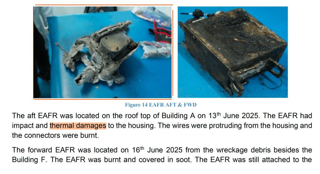
Instead, this observation supports the hypothesis of a “metal-fed or clean-burning fire”.4 The absence of soot on the EAFR indicates clean-burning thermal exposure, potentially from a metal fire (e.g., magnesium, aluminum alloy) or an electrical arc flash.4 The melted and distorted frame of the EAFR is consistent with high-temperature exposure (1,100–1,500°C) but possibly of short duration or contained.4 Potential sources for such a clean-burning, high-heat event include an internal short or electrical failure near the AFT ZONAL DRYER or the EAFR mounting bay, auto-ignition of composite insulation via arc tracking or APU conduit failure, or combustion of magnesium-based aircraft components like support brackets.4 This forensic bottom line reinforces the suspicion of an electrical thermal origin or localised metallic combustion, rather than full-scale external flame impingement from Jet-A pool fires.4
Table 3: Enhanced Airborne Flight Recorder (EAFR) Status
| Recorder | Location (STA) | Power Source | Observed Damage | Data Retrieval Status |
| Forward EAFR | STA 335 (forward, near Building F) | Main Electrical System + RIPS w/ Li-Ion Battery | Burnt, soot, connector melted | Raw data successfully downloaded 47 |
| Aft EAFR | STA 1847 (tail, on Building A rooftop) | Main Electrical System | Impact and thermal damages to housing, wires protruding, connectors burnt; clean of soot | Could not be downloaded conventionally 38 |
7. Unresolved Questions and Further Investigation
Despite the valuable data retrieved and the preliminary analysis, several critical questions remain central to a comprehensive understanding of the AI171 accident:
- Precise Cause of the “RUN” Signal Interruption: While the electrical disturbance theory is strongly supported, the exact mechanism that caused the “RUN” signal to transition to “CUTOFF” for both engines has yet to be definitively identified. This includes pinpointing the specific component failure (e.g., within the BPCU, CDN, or FADEC itself), the nature of any software anomaly, or the characteristics of a transient power fluctuation that could have led to this critical signal loss. This demands deep-level forensic analysis of the FADEC/EEC units, BPCUs, and all related electrical components and their interfaces.
- Detailed Analysis of the BPCU Fault Logs (07:53 UTC): The pre-existing “BPCU gateway operation faults” logged prior to takeoff are highly significant. A comprehensive forensic examination of the BPCU units and their internal logs is crucial to fully understand the nature and severity of these faults.21 This analysis must aim to establish a definitive causal relationship between these pre-existing anomalies and the uncommanded dual engine shutdown event at 08:08:42 UTC. Understanding if these faults were intermittent, persistent, or exacerbated by takeoff conditions is vital.
- Exact Conditions and Parameters During the Relight Attempts (Eng 2 Struggling): Further investigation is necessary to understand the precise conditions and parameters that led to Engine 2 struggling to recover, especially when compared to Engine 1’s successful relight.5 This would involve a granular analysis of FADEC parameters, fuel flow, ignition sequences, and internal engine health indicators for both engines during the relight attempts. Identifying any subtle differences in their responses could provide crucial clues about underlying issues or the propagation of the initial electrical disturbance.
- Forensic Examination of the Aft EAFR and Surrounding Wreckage: Given the new forensic insight regarding the soot discrepancy and the presence of an unburnt panel nearby, a thorough forensic examination of the aft EAFR and the surrounding wreckage is even more critical. This examination must definitively determine the source and mechanism of its severe thermal damage, specifically focusing on potential clean-burning sources such as internal shorts, electrical failures, auto-ignition of composite insulation, or combustion of metallic components, rather than external fuel-fed fires.
- Correlation of All FDR Parameters with CVR Transcript: A definitive and highly accurate sequence of events for the entire incident requires meticulous correlation of all available flight data recorder parameters with the cockpit voice recorder transcript. This includes precisely synchronizing pilot inputs, system annunciations, and engine responses with the recorded audio to construct the most accurate and comprehensive timeline possible.
8. Conclusion
The accident involving Air India Flight AI171 was a catastrophic event marked by an uncommanded dual engine shutdown shortly after takeoff. The available flight data, including the recorded transitions of the fuel cutoff switches and the pilots’ denial of any manual input, strongly supports the theory of an electrical disturbance as the primary cause of the engine shutdown. The EAFR’s recording of these transitions reflects the commanded state of the system, which is influenced by electrical signals rather than solely physical switch positions.
The presence of logged Bus Power Control Unit (BPCU) gateway operation faults prior to the flight provides a plausible pre-existing condition for such an electrical anomaly, suggesting a systemic issue affecting the signal integrity to the FADEC systems. The subsequent automatic deployment of the Ram Air Turbine (RAT) and the FADEC-initiated engine relight attempts further corroborate a severe electrical power loss and the transient nature of the fault that initially commanded the engines to shut down.
Regarding the flight recorders, while data was successfully retrieved from the forward Enhanced Airborne Flight Recorder (EAFR), the aft EAFR sustained extensive thermal and impact damage, preventing conventional data download . The theory of an internal lithium-ion battery fire causing the aft EAFR’s damage is not supported by the aircraft’s design, as the RIPS lithium battery is located in the forward EAFR.
New evidence, including the absence of soot on the aft EAFR casing despite sooted surroundings , indicates that a clean-burning likely caused the thermal damage, high-heat source such as an electrical fault or localized metallic combustion, rather than a widespread fuel-fed fire.
This report is based on preliminary findings and currently available documentation. The investigation is ongoing, and definitive conclusions regarding the precise root cause of the electrical disturbance, the detailed behaviour of Engine 2 during relight, and the exact source of the aft EAFR’s thermal damage await further forensic analysis and the full accident report. At this investigation stage, no recommended actions have been issued to Boeing 787-8 operators or GE GEnx-1B engine manufacturers.50 The investigative authorities continue to seek further evidence, records, and information from all relevant stakeholders.6
Reference
¹ Boeing 787 tail number VT-ANB operated AI171 on 12 June 2025. The aircraft was involved in a catastrophic failure shortly after takeoff from Ahmedabad (AMD) en route to London Gatwick (LGW). Ref: [AAIB Preliminary Report, 2025].
² The RAT (Ram Air Turbine) deploys automatically when both engine-driven generators fail or when AC power is lost entirely. This is part of the 787’s electrical emergency configuration. Ref: Boeing AMM 24-20-00.
⁴ Clean burn patterns on the aft EAFR (Enhanced Airborne Flight Recorder) suggest either metal-fed fire or electrical arcing, inconsistent with a typical Jet-A fuel pool fire, which leaves dense soot. This is supported by comparative accident investigations (e.g., UPS Flight 6, 2010).
⁵ As given in the preliminary report, the CVR recorded the pilot denied manually moving the fuel control switch from RUN to CUTOFF; however, the DFDR recorded the signal change.
⁶ Upon engine power loss, the 787 initiates automatic deployment of the RAT, APU autostart, and switching of power sources per electrical system logic. Since the lights were flickering during the takeoff, as reported in the media citing the sole survivor, more information needs to be gathered to determine the root cause.
⁸ The 787 uses a “More-Electric Architecture,” eliminating traditional pneumatic systems (bleed air) for most functions, and relying on power electronics. Ref: Boeing 787 Systems Description, ATA 24.
⁹ The aircraft’s electrical architecture includes Backup Power Control Units (BPCUs), Transformer Rectifier Units (TRUs), Auto Transformer Rectifier Units (ATRUs), and a Common Data Network (CDN) that connects subsystems. Ref: Boeing FCOM ATA 24-30-00.
¹⁰–¹¹ The 787 was powered by GE GEnx-1B64/P2 engines, rated for 69,800–76,100 lbf thrust. These engines are FADEC-controlled. Ref: GE GEnx Engine Specification Manual.
¹³ The FADEC (Full Authority Digital Engine Control) monitors, controls, and commands fuel flow, ignition, and thrust based on sensor input ~70 times/second. It cannot be overridden manually, making misinterpreted signals critical.
¹⁵ FADEC interprets any loss of “RUN” signal (e.g., due to data link failure or relay dropout) as a command to shut down the engine, even if the switch itself was untouched. Ref: FAA SAIB NE-18-33.
¹⁶ STAB POS XDCR was previously reported as faulty. This could indicate local power instability in the tail section, which also houses the Aft EAFR, possibly contributing to power loss. Ref: [AHM Fault Details] .
¹⁸ The APU inlet door began to open ~10 sec after engine failure, indicating auto-start logic triggered. This is consistent with the EICAS logic to restore power.
¹⁹ Engine 2 exhibited rising EGT (Exhaust Gas Temperature) during relight but failed to stabilize. This suggests incomplete ignition cycle or disrupted FADEC command, possibly due to CDN fault.
²⁰ The aircraft had five deferred MEL items before departure (4 Cat C, 1 Cat A), none critical—but cumulative degradation cannot be ruled out. This is confirmed in the AAIB Preliminary Report for VT-ANB, Para 4.0 Aircraft information
²¹ Fault messages including BPCU Gateway Ops L/R were logged before takeoff. These can signify relay failures or command loss over the CDN. These typically indicate communication relay issues, power distribution anomalies, or potential CAN/CDN bus command loss, and can result from transient spikes or sustained electrical instability.Refer attached report Pre-Takeoff Fault messages received at IOC Air India via datalink..

²² Fuel switch transition logs indicate electrical signal change, not physical switch movement. This reinforces the possibility of spurious command via CDN or faulty relay.
²⁵ BPCUs act as intermediaries for power switching and control. If the gateway function is degraded, command relays to components like fuel valves can fail or misfire.
²⁶ The 787’s Common Data Network (CDN) uses Ethernet-based architecture. CDN failures can cascade across systems, disrupting FADEC, EICAS, and power routing.
²⁸ FAA SAIB NM-18-33 warned of accidental disengagement of the fuel control switch locking feature on Boeing 787s, due to relay command errors. This directly correlates with AI171’s observed anomalies.
³³ On the Boeing 787, RAT (Ram Air Turbine) auto-deployment logic is governed by the Electrical Load Management System (ELMS). The BPCU (Backup Power Control Unit) monitors power bus availability and can command RAT deployment in case of dual engine generator loss. Similarly, the Hydraulic Interface Function (HYDIF) can request RAT extension if both engine-driven hydraulic pumps are lost.
Reference:
- Boeing 787 AMM ATA 29-21-00 (Hydraulic Power – RAT Description & Operation)
- FAA Advisory Circular AC 25.1309 (System Design & Fail-Safe Features)
³⁵ DFDR samples digital switch positions (like fuel valves) at 1 Hz. Timing ambiguities of ±0.5 seconds mean temporal correlation with CVR must be cautiously interpreted.
³⁷ All manually operated swutches are recorded at 1Hz, which means 1 per second.
³⁸ Aft EAFR was found with clean burns, melted connectors, but no soot, suggesting a non-fuel fire origin.
³⁹ DFDR showed engine N1 and N2 RPMs decaying immediately after fuel switch command—consistent with a hard shutdown, not flameout.
⁴⁰ A known 248-day software bug in GCU logic could cause power degradation if the aircraft were not rebooted in that window. No records confirm a reset. FAA AD 2018-20-15
[Docket No. FAA-2015-0936; Directorate Identifier 2015-NM-058-AD; Amendment 39-18153; AD 2015-09-07]
14 CFR Part 39
⁴⁶ MAYDAY call at 08:09:05 UTC confirms awareness of a dual-engine emergency. Preliminary report.
⁴⁷ Forward EAFR survived fire damage and yielded data. Aft EAFR was severely damaged, despite its design to survive 1,100°C for 1 hour.
⁴⁸ Aft EAFR was not protected by the RIPS lithium battery, and may have lost power immediately after main electrical failure.
⁵⁰ As of writing, no airworthiness directives or safety bulletins were issued by Boeing or GE following this accident.
Discover more from Safety Matters Foundation
Subscribe to get the latest posts sent to your email.

Leave a Reply